Double Straight-Line Effect in Slug Tests
by Glenn M. Duffield, President, HydroSOLVE, Inc.
What Is The
Double Straight-Line Effect?
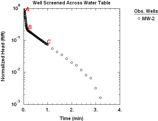
When you apply the method of Bouwer and Rice (1976) or Hvorslev (1951) for slug test analysis, you expect to identify a single straight line from the data. When the control well used for the test is screened across the water table, however, the response data may give the appearance of two straight lines on a plot of log normalized head vs. time (Bouwer 1989).

In Figure 1, the initial, steeper straight-line segment (A-B) represents drainage of water from the filter pack. A second, less steep straight-line segment (B-C) develops after the initial filter pack drainage and represents the response of the aquifer.
Note that data from slug tests in certain wells screened below the water table (i.e., fully submerged) may exhibit curvature that is unrelated to the double-straight line effect.
Estimating
Hydraulic Conductivity
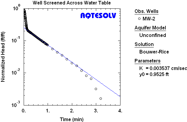
You can use Bouwer and Rice (1976) solution to analyze slug tests performed in wells screened across the water table. As shown in Figure 2, the Bouwer-Rice straight line is fit to the second straight-line data segment to estimate the hydraulic conductivity of the aquifer.

For wells screened across the water table, Bouwer (1989) recommends correcting the casing radius for the effective porosity of the filter pack before performing any calculations as follows:
where is the corrected casing radius [L], is effective porosity (specific yield) of the filter pack [dimensionless], is nominal casing radius [L] and is the well radius [L].
Note that the well radius is typically taken as the borehole radius (i.e., extending to the outer radius of the filter pack) when the filter pack is expected to be more conductive than the aquifer.
= = 7.6 cm
width of annular space containing filter pack = 5.1 cm
estimated effective porosity of filter pack = 0.3 (= 30%)
= 7.6 cm + 5.1 cm = 12.7 cm
= [(0.7)(7.6 cm)2 + (0.3)(12.7 cm)2]½ = 9.4 cm
Butler (1998) presents alternate methods to correct for filter pack drainage in wells screened across the water table.
Slug test analysis software can correct the casing radius for you if a well is screened across the water table.