Barker Solution for Nonleaky Confined Aquifers

A mathematical solution by Barker (1988) known as the generalized radial flow (GRF) model is useful for determining the hydraulic properties of single- and double-porosity aquifers. Analysis involves matching the Barker solution to drawdown data collected during a pumping test.
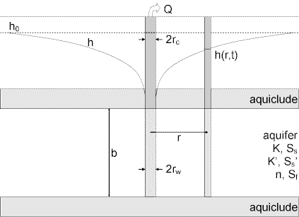
The GRF model may be used to simulate unsteady, n-dimensional flow to a fully penetrating source in an isotropic nonleaky confined aquifer. The source is an n-dimensional sphere (projected through three-dimensional space) of finite radius (), storage capacity () and skin factor ().
You are not restricted to constant-rate tests with the Barker solution. Using the principle of superposition in time, AQTESOLV can simulate variable-rate and recovery tests with this method.
Assumptions
- aquifer has infinite extent
- aquifer is homogeneous, isotropic and of uniform extent of flow region
- potentiometric surface is initially horizontal
- aquifer is confined
- flow is unsteady
- wells are fully penetrating
- water is released instantaneously from storage with decline of hydraulic head
Equations
Barker (1988) derived a generalized radial flow model for unsteady, -dimensional flow to a fully penetrating source in an isotropic nonleaky confined aquifer. The spatial dimension, , determines the change in conduit area with distance from the source (Doe 1990). In a two-dimensional system (=2), the source is a finite cylinder, the typical configuration for analyzing cylindrical flow to a well.
The Laplace transform solution for drawdown in the pumped well (source) is as follows:
The following equation is the Laplace transform solution for drawdown in an observation well:
where
- is extent of flow region [L]
- is hydraulic head at time [L]
- is hydraulic conductivity [L/T]
- is modified Bessel function of second kind, order
- is flow dimension [dimensionless]
- is the Laplace transform variable
- is pumping rate [L³/T]
- is radial distance from pumping well to observation well [L]
- is casing radius [L]
- is well radius [L]
- is specific storage [dimensionless]
- is wellbore skin factor [dimensionless]
- is elapsed time since start of pumping [T]
The parameter , the flow region extent, has a simple interpretation for integral flow dimensions.
- For =1 (one-dimensional flow), is the square root of the conduit flow area (normal to the flow direction).
- For =2 (two-dimensional radial flow), is the thickness of the aquifer.
- For =3 (spherical flow), the parameter , which is raised to the power of 3-, has no significance.
For nonintegral flow dimensions, has no simple interpretation (Barker 1988).
In the Laplace transform solution, is limited to positive values; however, using the effective well radius concept, we also may simulate a negative skin (Hurst, Clark and Brauer 1969).
If you enter a radius for downhole equipment, AQTESOLV uses the effective casing radius instead of the nominal casing radius in the equations for this solution.
Data Requirements
- pumping and observation well locations
- pumping rate(s)
- observation well measurements (time and displacement)
- casing radius and wellbore radius for pumping well(s)
- downhole equipment radius (optional)
- extent of flow region
Solution Options
- constant or variable pumping rate with recovery
- multiple pumping wells
- multiple observation wells
- boundaries
Estimated Parameters
AQTESOLV provides visual and automatic methods for matching the Barker method to data from pumping tests and recovery tests. The estimated aquifer properties are as follows:
- (hydraulic conductivity)
- (specific storage)
- (flow dimension)
- (flow region extent)
- (dimensionless wellbore skin factor)
- (well radius)
- (nominal casing radius)
Curve Matching Tips
- Use radial flow plots to help diagnose wellbore storage.
- Use linear flow plots to help diagnose linear flow.
- Match the Cooper and Jacob (1946) solution to late-time data to obtain preliminary estimates of aquifer properties.
- Match early-time data affected by wellbore storage by adjusting with parameter tweaking.
- If you estimate for the test well, the estimated value replaces the nominal casing radius and AQTESOLV still performs the correction for downhole equipment.
- Choose Match>Visual to perform visual curve matching using the procedure for type curve solutions.
- Use active type curves for more effective visual matching with variable-rate pumping tests.
- Select values of and from the Family and Curve drop-down lists on the toolbar.
- Use parameter tweaking to perform visual curve matching and sensitivity analysis.
- Perform visual curve matching prior to automatic estimation to obtain reasonable starting values for the aquifer properties.
References
Barker, J.A., 1988. A generalized radial flow model for hydraulic tests in fractured rock, Water Resources Research, vol. 24, no. 10, pp. 1796-1804.
Moench, A.F., 1984. Double-porosity models for a fissured groundwater reservoir with fracture skin, Water Resources Research, vol. 20, no. 7, pp. 831-846.