Pumping Tests
by Glenn M. Duffield, President, HydroSOLVE, Inc.
What Is A
Pumping Test?
A pumping test is a field experiment in which a well is pumped at a controlled rate and water-level response (drawdown) is measured in one or more surrounding observation wells and optionally in the pumped well (control well) itself; response data from pumping tests are used to estimate the hydraulic properties of aquifers, evaluate well performance and identify aquifer boundaries. Aquifer test and aquifer performance test (APT) are alternate designations for a pumping test. In petroleum engineering, a pumping test is referred to as a drawdown test.
Pumping Test or Pump Test? Although the terms pumping test and pump test are often applied interchangeably, the use of pumping test is preferred (Woessner and Anderson 2002). If you're testing the performance of a pump, use pump test; if you're testing the performance of an aquifer through the action of pumping a well, use pumping test.
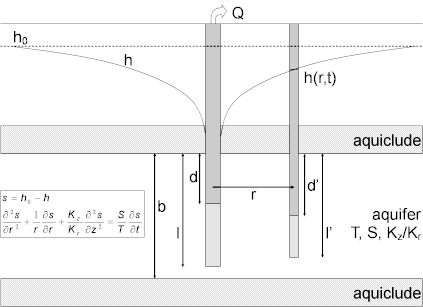
The goal of a pumping test, as in any aquifer test, is to estimate hydraulic properties of an aquifer system. For the pumped aquifer, one seeks to determine transmissivity, hydraulic conductivity (horizontal and vertical) and storativity (storage coefficient). In layered systems, one also uses pumping tests to estimate the properties of aquitards (vertical hydraulic conductivity and specific storage). Pumping tests can identify and locate recharge and no-flow boundaries that may limit the lateral extent of aquifers as well.
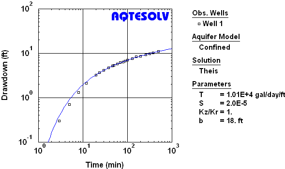
Typically, aquifer properties are estimated from a constant-rate pumping test by fitting mathematical models (type curves) to drawdown data through a procedure known as curve matching (Figure 2). Diagnostic tools such as derivative analysis are useful for identifying flow regimes and aquifer boundaries from a pumping test prior to performing curve matching.
Prior to performing a pumping test in the field, one should spend time in the office developing a thorough plan for the test. Proper planning includes the design of the test, acquisition and preparation of field equipment, measurement and control of flow rates, measurement locations and schedules (with pre- and post-test collection periods) for water levels, disposal of pumped water and test duration.
Types Of
Pumping Tests
Common types of pumping tests that you may perform include the following:
- Constant-rate tests maintain pumping at the control well at a constant rate. This is the most commonly used pumping test method for obtaining estimates of aquifer properties.
- Step-drawdown tests proceed through a sequence of constant-rate steps at the control well to determine well performance characteristics such as well loss and well efficiency.
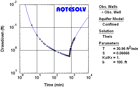
- Recovery tests use water-level (residual drawdown) measurements after the termination of pumping. Although often interpreted separately, a recovery test is an integral part of any pumping test.
Designing A
Pumping Test
The following reconnaissance work and planning should factor into the design of a pumping test:
- best time of year for pumping test
- geology of pertinent aquifer and aquitard units
- natural agents of groundwater fluctuation such as barometric pressure changes, earth tides and tidal variations which may affect water levels in observation wells during the pumping test
- off-site groundwater users which may influence water levels during the pumping test
- location and construction details of new and existing wells
- depth setting and type of pump in control well
- pumping duration and rate
- pumping rate measurement and control
- water-level measurement and frequency
- strategy for disposal of pumped water
- collection of water quality samples during pumping
- estimates of aquifer properties from previous work or literature data
- location and orientation of streams, faults, lithologic contacts and other potential aquifer boundaries
- potential for salt water intrusion in coastal areas
- field equipment
- prediction of pumping test response
- impact of pumping test on nearby water users
Field Equipment Checklist
Consider taking the following items into the field with you on your next pumping test assignment:
- generator, power inverter and extension cords
- submersible pump
- discharge pipe, connections, reducers/enlargers
- flow measurement device(s)
- tape measure(s)
- pressure transducer(s), cables, data logger(s)
- electric water-level sounder(s) and batteries
- steel tape(s) and carpenter's chalk
- watches/stopwatches
- barometric sensor
- thermometer
- pH and conductivity meters
- sample bottles
- keys for wellhead locks and other infrastructure
- toolkit, electrical tape, rope, wire ties, heat shrinks, duct tape, tarp, paper towels
- lubricant/penetrating oil (e.g., WD-40)
- flashlights/lanterns
- data collection forms, log book, permanent-ink pens
- computer, calculator
- graph paper (semilog, log) and/or computer software
- references, standard operating procedures
- manufacturer's operating manuals for equipment
- maps (site, geologic and topographic), cross section(s)
The foregoing equipment list is provided as a general guide for a typical pumping test and should not be considered exhaustive. Modify or supplement the list to meet the requirements of your specific test and field conditions. Please send us your suggestions for additions to the list!
Pumping Rate Measurement And Control
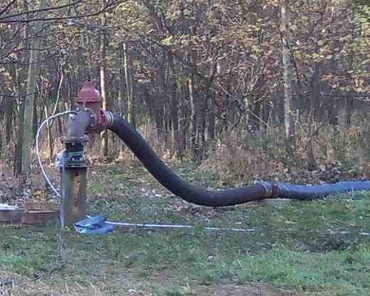
A controlled pumping stress is imposed on an aquifer system during a pumping test. Therefore, carefully measuring, controlling and recording the flow rate throughout the test is essential for a successful outcome.
Although a constant pumping rate is most often the goal, the rate may vary during a pumping test. Software such as AQTESOLV can account for variable pumping rates; however, results will depend on how closely the recorded flow rates correspond to actual rate changes.
Rate Measurement
Measuring the flow rate during a pumping test can be accomplished in a number of ways including the following:
- calibrated container and stopwatch
- in-line flowmeter
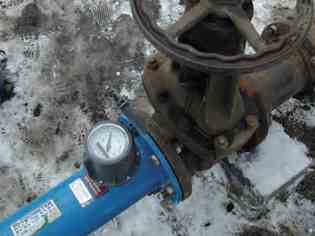
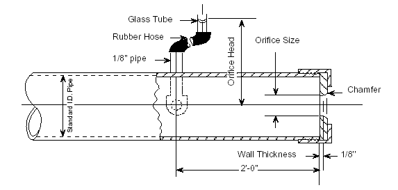
- orifice weir
- weir or flume
Flow rates should be recorded with sufficient frequency to demonstrate a constant rate or to monitor planned rate changes. In the event of temporary test interruption (e.g., power failure), pumping stop and restart times should be noted to allow for proper interpretation of the test. Bear in mind that the discharge rate often decreases with time as the water level in the control well drops. Kruseman and de Ridder (1994) recommend checking and, if necessary, adjusting the flow rate at least once every hour; however, one should consider more frequent measurements until it becomes evident how often rate adjustments are required (Stallman 1971).
Estimating discharge from a pumped well by use of a circular orifice weir (USGS 2010)
Rate Control
Controlling the flow rate is also important for a successful pumping test. As a general rule, Stallman (1971) recommends controlling the pumping rate within ±10% for a constant-rate test or for each constant-rate step. USBR (1995) suggests a tolerance of ±5% for the pumping rate. State and local regulations may offer additional guidance regarding an acceptable tolerance for rate variation during a pumping test.
Water-Level Measurement
Measuring Water Levels
During a pumping test, water levels in wells may be measured by means of manual techniques or through the use of sensors with data loggers.
Manual Methods
Manual water-level measurement techniques include chalked steel tape, electric water-level sounders and air line methods.
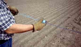
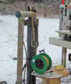
The USGS has published procedural documents for measuring water levels with graduated steel tapes and electric tapes:
- Measuring water levels by use of a graduated steel tape (USGS 2010)
- Measuring water levels by use of an electric tape (USGS 2010)
Steel tapes are not recommended for taking water-level measurements in the pumped well owing to rapid water-level drawdown and the possibility of cascading water in the well.
When taking manual measurements in the pumped well, be sure to secure the measuring device when sounding the well to prevent accidental entanglement with the pump.
Data Loggers
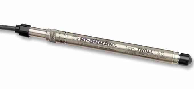
Pressure transducers combined with data loggers provide rapid and accurate measurements of water levels in wells.
Even when working with reliable transducers and data loggers, it's good practice to obtain periodic manual measurements at each observation well to (1) confirm transducer readings and (2) provide backup readings in the event of accidental data loss.
Measurement Frequency
A logarithmic schedule is appropriate for recording water levels a during a constant-rate pumping test. For variable-rate tests (e.g., during recovery or step-drawdown tests), logarithmic sampling should restart for each change in rate. You can find recommended schedules for manual water-level measurements in Driscoll (1986) and Kruseman and de Ridder (1994).
Pressure transducers are available in vented and nonvented models (e.g., In-Situ, Inc.). Vented transducers measure pressure relative to the ambient barometric pressure. Nonvented transducers measure absolute pressure including the pressure of the air column above the sensor. A barometric sensor is required to correct readings from nonvented transducers for changes in barometric (air) pressure.
For any pumping test, an on-site barometric sensor is recommended in the event that water levels require correction for barometric efficiency.
Most modern data loggers have an option for logarithmic sampling; however, you may convert measurements from a linear to a logarithmic schedule with software such as AQTESOLV.
Pre- And Post-Test Water Levels
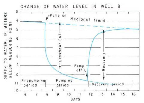
Pre- and post-test water-level measurements are essential for the identification of trends (e.g., barometric fluctuations) that may require correction prior to pumping test data interpretation. A linear schedule is recommended for monitoring water levels before and after the test. Pre-test water-level measurements should begin at least several days before pumping begins (Figure 5).
Disposal Of
Pumped Water
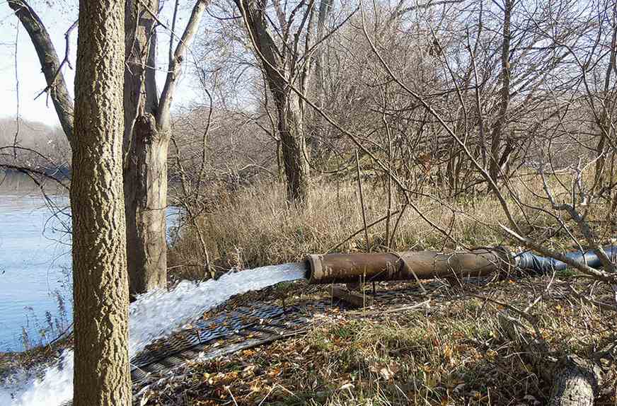
In the case of a pumping test that extracts water from an aquifer, care should be exercised in the disposal of the pumped water. First and foremost, be certain that you dispose of the water in accordance with any applicable laws and regulations.
Bear in mind the following considerations as you weigh options for the disposal of discharge water:
- Avoid direct discharge of water on the ground surface if the water is likely to recharge the pumped aquifer (e.g., a shallow unconfined aquifer or karst aquifer with sinkholes). Recycling of the pumped water through recharge can result in the false identification of a constant-head boundary or leakage.
- Discharge of water to a surface water feature such as a stream is a viable option if it is anticipated that the surface water body is hydraulically disconnected from the pumped aquifer or if it behaves as a constant-head boundary.
- Avoid adverse thermal, biological, water-quality, erosion or sediment mobilization impacts when discharging to groundwater or surface water and obtain appropriate discharge permits.
In the design phase of a pumping test, you may consider using a software tool like AQTESOLV to evaluate the effect of pumped water disposal on observation well response by performing forward (predictive) simulations for different well/aquifer scenarios.
Test Duration
The decision to terminate a pumping test is best made on the basis of hydrogeologic conditions at the test site and the objectives of the test. Longer tests may be necessary to estimate specific yield in an unconfined aquifer or to observe boundary effects.
Plotting and inspecting pumping test data as they are collected in the field can help you to decide when it's appropriate to end a pumping test.
- Have the objectives of the test been achieved?
- Have sufficient late-time data been collected to estimate specific yield in an unconfined aquifer?
- Has the test continued long enough to detect and locate aquifer boundaries?
Other factors may influence the planned duration of a pumping test including budgetary constraints and regulatory requirements. Often, applicable regulations may establish a minimum duration required for a test, but longer tests may be necessary to achieve other test objectives.
Well Network
The network of wells used for monitoring water-level response during a pumping test should ideally include, in addition to the control well, new and/or existing observation wells with positions and depths strategically chosen to provide drawdown response suitable for estimating desired aquifer and aquitard properties.
Estimating Vertical Hydraulic Conductivity (Kz)
Estimation of the vertical hydraulic conductivity, , of a nonleaky or leaky confined aquifer requires pumping and observation wells that are partially penetrating. Hantush (1961a) showed that the effect of partial penetration becomes negligible at radial distances given by the following equation:
where is radial distance from the control well [L], is saturated aquifer thickness [L] and is vertical to horizontal hydraulic conductivity anisotropy ratio [-].
Use the following calculator to compute the radial distance from the control well at which partial penetration may be ignored.
Additional
Resources
Links To Guidance Documents
- British Columbia Ministry of Environment
- Michigan Department of Environmental Quality
- New Hampshire Department of Environmental Services [pdf]
- New Jersey Department of Environmental Protection
- New York Department of Environmental Conservation
- New Zealand Environment Waikato
- North Carolina Division of Environmental Quality
- Ohio Environmental Protection Agency
- Oregon Water Resources Department [pdf]
- U.S. Environmental Protection Agency [pdf]
- Virginia Department of Environmental Quality
Find additional guidelines and procedures in the collection of guidance documents.
Recommended Reading
- Analysis and Evaluation of Pumping Test Data (Kruseman and de Ridder 1994)
- Hydraulics of Wells (Hantush 1964)
- Theory of Aquifer Tests (Ferris et al. 1962)
- Aquifer-Test Design, Observation and Data Analysis (Stallman 1971)
- Ground-Water Hydraulics (Lohman 1972)
Find additional pumping test literature in the list of aquifer testing references.